TI LP-MSPM0G3519
Jump to navigation
Jump to search

This article describes specifics for the TI LP-MSPM0G3519 evaluation board. It can be used to test & verify MSPM0L111x device support.
Preparing for J-Link
- Remove SWDIO, SWCLK and NRST jumpers of J19.
- Solder 10-pin connector to J21 place.
- Connect the J-Link to the SWD header J21.
- Power the board via the USB connector of the break out board.
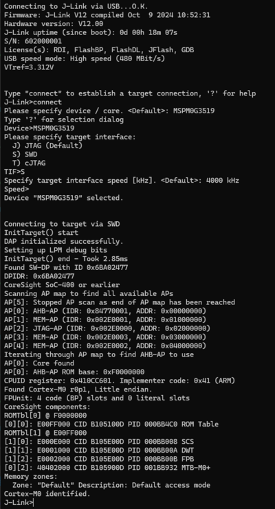
- Verify the Connection with e.g. J-Link Commander. The output should look as follows:

Example Project
The following example project was created with the SEGGER Embedded Studio project wizard and runs out-of-the-box on the TI LP-MSPM0G3519. It is a simple Hello World sample linked into the internal flash.
SETUP
- Embedded Studio: V8.16a
- Hardware: TI LP-MSPM0G3519
- Link: File:TI LP MSPM0G3519 TestProject ES V816a.zip